Physical Address
304 North Cardinal St.
Dorchester Center, MA 02124
Physical Address
304 North Cardinal St.
Dorchester Center, MA 02124

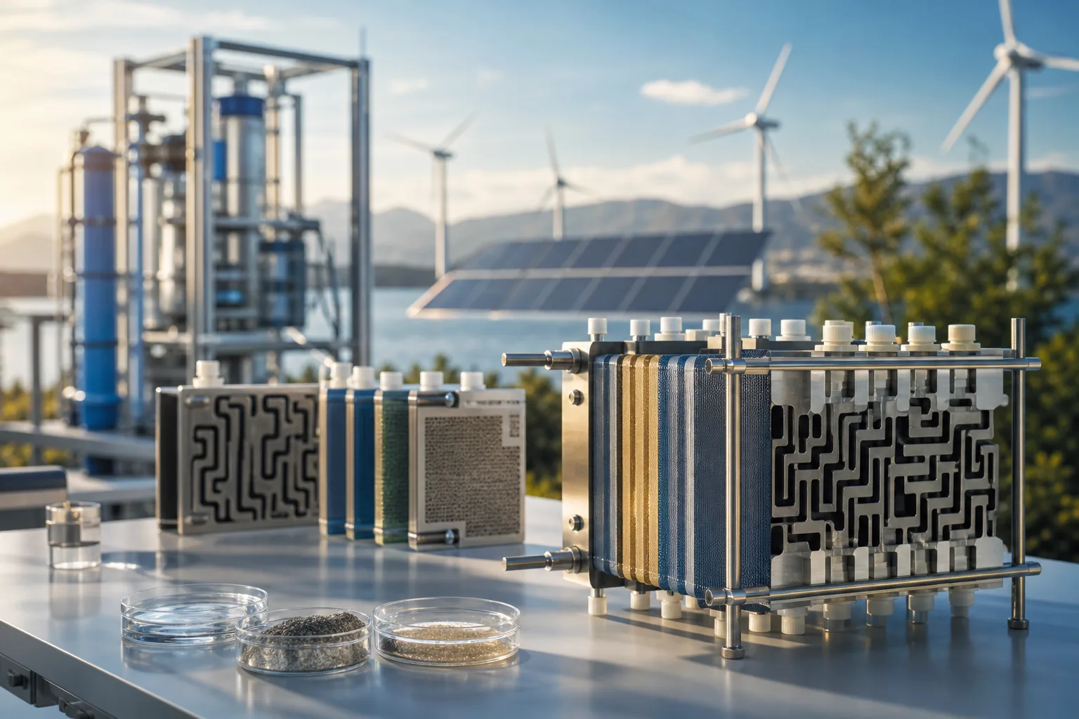
Explore how new reverse electrodialysis stack designs tackle scale-up limits and feed variability to sustain efficient electricity generation in large-scale plants.
You arrive at the plant with salinity, flow, and impurity conditions already shifting. Yet your electrical output forecast still needs to hold, and your maintenance plan can’t depend on cleaning a stack every few days. Reverse electrodialysis stack design must account for how controlled mixing between water bodies of different salinities generates electricity, according to Tethys Engineering. The practical difficulty begins when feed conditions refuse to stay uniform.
Most desalination projects don’t have a membrane-selection problem. They have a scale-up and operating-window problem. When a plant engineer discusses reverse electrodialysis stack design, the real question is whether useful net output survives larger stacks, variable hydraulics, scaling, and service demands. Research in Processes identifies a negative scale factor that can limit large-scale power generation, so conventional scale-up deserves scrutiny. The review focuses on the membrane, flow-path, electrical, cleanability, and pilot-data decisions relevant to Singapore projects and MediSun Energy’s integrated brine-management approach. It also separates emerging research directions from proven commercial answers.
You may find that a RED stack performs well as a small unit yet loses practical value when you add more units, longer flow paths, and larger electrical loads. You need to examine net output, service access, and feed variability because simply enlarging the same stack doesn’t answer those questions.

When you review the research, Processes reported that progress in reverse electrodialysis had stagnated for nearly a decade, according to the publisher’s 18 November 2025 perspective. You can now see attention moving from incremental membrane and spacer optimisation toward architecture-level designs that aim to retain small-unit efficiency inside larger assemblies.
When you assess Joost Veerman’s 18 November 2025 Processes perspective, you’ll find a bioinspired, fractal RED architecture. You can think of its core idea as hierarchical organisation: many small RED elements operate cooperatively rather than behaving as one enlarged unit. Processes describes this arrangement as a way to preserve and amplify small-unit efficiency, although you should treat it as a proposed direction, not a validated commercial performance guarantee.
Weak example: “Increase the stack from 20 to 200 cell pairs and keep the same flow arrangement.”
Stronger direction: “Operate 10 modular RED branches, each with 20 cell pairs, using coordinated manifolds and separately monitored electrical outputs.”
When you examine the 2026 research listings on electrode segmentation and gypsum and silica impurities, you’ll see a broader scale-up problem. You need to account for electrical collection and feed chemistry as much as membrane area. When you read the accompanying chart, you’ll see conventional small-unit efficiency and fractal-inspired preservation and amplification assigned a relative value of 1. That distinguishes the established reference from the proposed response. It doesn’t claim measured superiority.
If you operate a desalination plant, you need dependable output despite changing brine chemistry and scaling risk. If you’re an industrial manufacturer, you must balance waste reduction with impurity control. Engineering firms need to make tighter integration and service decisions, while public infrastructure planners need evidence that complex architectures will remain maintainable. You can work with MediSun Energy to connect RED with brine-to-value and resource recovery projects, but pilot data is still needed before any architecture earns a commercial design basis.
Practical rule: Compare any larger RED concept with a monitored small-unit baseline before approving architecture-level scale-up.
A RED stack does more than place membranes in alternating order. Processes describes a core arrangement of alternating anion-exchange and cation-exchange membranes, while porous spacers provide access to both feedwater compartments, according to its 18 November 2025 research. The design basis starts with membrane pairs, but it can’t stop there.

Each spacer must distribute feedwater and promote mixing, not merely hold membranes apart. Flow distribution, pressure drop, concentration polarisation, and service access need to be judged together. That’s where scale-up trade-offs become visible.
High- and low-concentration compartments drive ion movement through alternating membranes. Spacers separate these compartments, while the Fe2+/Fe3+ redox couple converts stack ion current into electrical current at the electrodes, according to research published in Processes on 18 November 2025.
The supplied component inventory counts 2 membrane types, 2 feedwater compartments, 2 spacer functions, and 1 electrode current-conversion system. That count describes functions, not performance. It shouldn’t be treated as a power-density ranking.
The low-concentration compartment can dominate ohmic resistance, especially when its flow path becomes longer or poorly distributed. Spacer geometry must provide feedwater access and mixing, yet it can also increase pressure drop and encourage stagnant zones.
Weak setup: A 20-metre cross-flow path uses one spacer geometry across every compartment, with no local pressure or conductivity checks.
Stronger setup: A pilot maps inlet distribution, pressure drop, conductivity, and outlet salinity separately for the low- and high-concentration paths before stack expansion.
Electrical output depends on more than membrane area. Conventional cross-flow scale-up increases hydraulic and electrical losses across one larger unit, while modular aggregation preserves smaller flow paths and creates more interfaces for controls and maintenance.
| what changed | before | after | who it affects |
|---|---|---|---|
| Intermembrane architecture | Conventional planar low- and high-concentration compartments separated by porous spacers | Fractal geometries proposed within intermembrane compartments, especially the higher-resistance low-concentration side | Stack designers and membrane-hydraulics engineers |
| System aggregation | Scale a single cross-flow stack toward larger dimensions | Aggregate numerous cross-flow stacks as modular large-scale assemblies | Plant integrators and infrastructure planners |
| Flow and mixing function | Spacers provide feedwater access and mixing in each compartment | Flow-path concepts aim to preserve distribution and mixing while managing resistance at larger scale | Desalination operators and process engineers |
| Electrical collection | Ion current is converted at the electrode system | Electrode behaviour and segmentation require dedicated scale-up and pilot assessment | Electrical, controls, and maintenance teams |
Brine chemistry can turn poor distribution into gypsum or silica deposition, impurity fouling, and shorter cleaning intervals. Electrode segmentation may limit the impact of a fault, but voltage losses, fouling, scaling, and maintenance intervals still require pilot validation.
Practical rule: Compare each larger RED architecture with a monitored small-unit baseline before approving its design basis.
Laboratory results can hide a serious project risk: changing brine or industrial waste chemistry may alter flow distribution, electrical output, scaling, and cleaning demand at the same time. A useful pilot must test these conditions together rather than split them into separate work packages.
Small-stack performance is a starting point, not a design guarantee. For Singapore projects, the first decision is whether the real feed can sustain useful net output while remaining inspectable, cleanable, and maintainable.

Don’t extrapolate performance until the pilot exposes the feed to representative impurities, pressure drop, electrode behaviour, and cleaning cycles. Gypsum, silica, and other contaminants may change both resource-recovery value and maintenance burden.
You need one evidence trail from feed characterisation to cleaning interval, not a peak-power figure isolated from operating conditions.
Processes reported on 18 November 2025 that active Ag/AgCl electrodes require feedwater switching after some operating time to reverse the process. Activated-carbon capacitive electrodes also require periodic current reversal after saturation, according to the same source and date. Neither electrode approach is universally superior, so test its cycle requirements in the intended feed.
A compact design may produce higher peak output yet lose value when pressure drop, scaling, or frequent cleaning reduces net production. MediSun Energy can apply this evidence-led sequence when integrating RED with brine management and CO₂ mineralization, although each feed still requires its own pilot validation.
The current design debate starts with a simple proposition: salinity differences contain usable Gibbs free energy. As ions move through alternating cation- and anion-exchange membranes, the stack separates high- and low-salinity streams and creates an electrical potential.
The principle is established. The difficulty appears when the equipment gets larger. A membrane arrangement that performs well in a small test stack may lose efficiency when longer flow paths, greater resistance, uneven distribution, and plant integration enter the design.

A typical design uses repeated membrane pairs to create adjacent high- and low-salinity compartments. Tethys Engineering describes RED as an arrangement of several cation- and anion-exchange membranes forming these alternating compartments, with electrodes completing the electrical circuit.
Weak configuration: A 10-pair RED stack uses flat membranes, one long parallel flow path, and a single outlet header.
Strong configuration: A 10-pair RED stack uses defined membrane pairs, profiled flow compartments, separate high- and low-salinity headers, and electrode zones sized for measured current distribution.
Improving spacer geometry, membrane profiles, and flow distribution at laboratory scale doesn’t guarantee that those gains will survive enlargement. The unresolved issue is a negative scale factor: as the system grows, ohmic resistance, pressure loss, dead zones, and manifold imbalance can increase faster than useful power output.
The 2025 Processes perspective identifies fractal geometry inside intermembrane compartments as one proposed route, with particular attention to the river-water compartment because it typically has the highest ohmic resistance.
The research reset focuses on organisation, not only better materials. Intermembrane fractal structures aim to shorten effective transport paths, while modular cross-flow aggregation aims to preserve manageable hydraulic and electrical behaviour as a plant expands. Neither approach is proven here at commercial scale or in Singapore.
The accompanying chart records 1 conceptual route for fractal geometry within intermembrane compartments and 1 for modular aggregation of cross-flow stacks. These are design directions, not performance guarantees. Pilot data must still test resistance, flow balance, scaling, cleaning recovery, and net electrical output before either architecture supports a larger project.
A screening method should connect Singapore feed conditions to a real RED integration decision. A promising stack concept means little if brine chemistry, hydraulic limits, and the resource-recovery target remain undefined.
Start with one page, not a full plant model. It should show whether the proposed stack deserves pilot funding and which evidence is still missing.
Record the desalination brine or industrial waste stream, including salinity, temperature, flow, suspended solids, and likely gypsum or silica exposure. Define the intended service too, such as brine concentration, resource recovery, or decarbonizing desalination.
Map the AEM-CEM pair, compartment arrangement, spacer choice, electrode configuration, expected pressure drop, and flow direction. Processes outlined 2 conceptual routes for fractal reverse electrodialysis system design, published on 18 November 2025.
Weak: “Use a standard membrane pair and optimise flow later.”
Strong: “Test the selected AEM-CEM pair at the recorded brine temperature, with a defined spacer, cross-flow rate, electrode arrangement, and pressure-drop limit.”
Model gross and net electrical output, then test impurity effects, voltage losses, electrode behaviour, cleaning response, and maintenance intervals. Don’t extrapolate small-stack performance until those results exist. Processes also describes modular aggregation of cross-flow stacks as a route whose performance may scale with unit count.
If you want a faster way to assess RED integration, MediSun Energy develops brine-management and resource-recovery pathways using Reverse Electrodialysis and CO₂ mineralization for desalination operators, industrial manufacturers, and engineering partners. Its project context is available in the MediSun Energy technology and project articles.